Headphone Speaker Wiring Diagram - How to Wire A Four Pole Headphone Jack | My Wiring DIagram : Related searches for headphone speaker wire diagram wire speaker to headphone jackspeaker wire to headphone adapterheadphone jack wireheadphone jack to speakersspeaker to headphone adapterwireless headphones with speakerspeaker output to headphone adapterconnect.
Headphone Speaker Wiring Diagram - How to Wire A Four Pole Headphone Jack | My Wiring DIagram : Related searches for headphone speaker wire diagram wire speaker to headphone jackspeaker wire to headphone adapterheadphone jack wireheadphone jack to speakersspeaker to headphone adapterwireless headphones with speakerspeaker output to headphone adapterconnect.. The idevice needs to see a resistance in the neighborhood of 5k between the microphone conductor and ground. The speaker wiring diagram and connection guide the basics you. Headphone with mic wiring diagram. A wiring diagram is a straightforward visual representation of the physical connections and physical layout associated with an electrical system or circuit. Speakers also have a wattage rating which indicates how much power from the amp they can handle before being damaged.
4 pole headphone jack with mic wiring diagram. A wiring diagram is a straightforward visual representation of the physical connections and physical layout associated with an electrical system or circuit. By ahmad jamaluddin february 12, 2020 post a comment. Wiring diagram usb to headphone jack wiring diagram 9 out of 10 based on 10 ratings. Headphones microphone telex wiring diagram audio png.
installing headphone jack - background noise now. pls help ... from media.fotki.com Speaker jack socket wiring your speakers in series like this will give you the following impedances: Adjoining wire routes could be revealed roughly, where particular receptacles or components need to be on a common circuit. How to fix my karaoke microphone. We have gathered numerous photos, hopefully this picture works for you, and also assist you in finding the response you are seeking. 2 x 4 ohm speakers = 8 ohm load 2 x 8 ohm speakers = 16 ohm load 2 x 16 ohm speakers = 32 ohm load. By ahmad jamaluddin february 12, 2020 post a comment. As always, be careful with your wiring, double check everything, and check that the schematic and drawing above actually make sense. If there is a pictures that violates the rules or you want to give criticism and suggestions about headphone jack with mic wiring diagram.
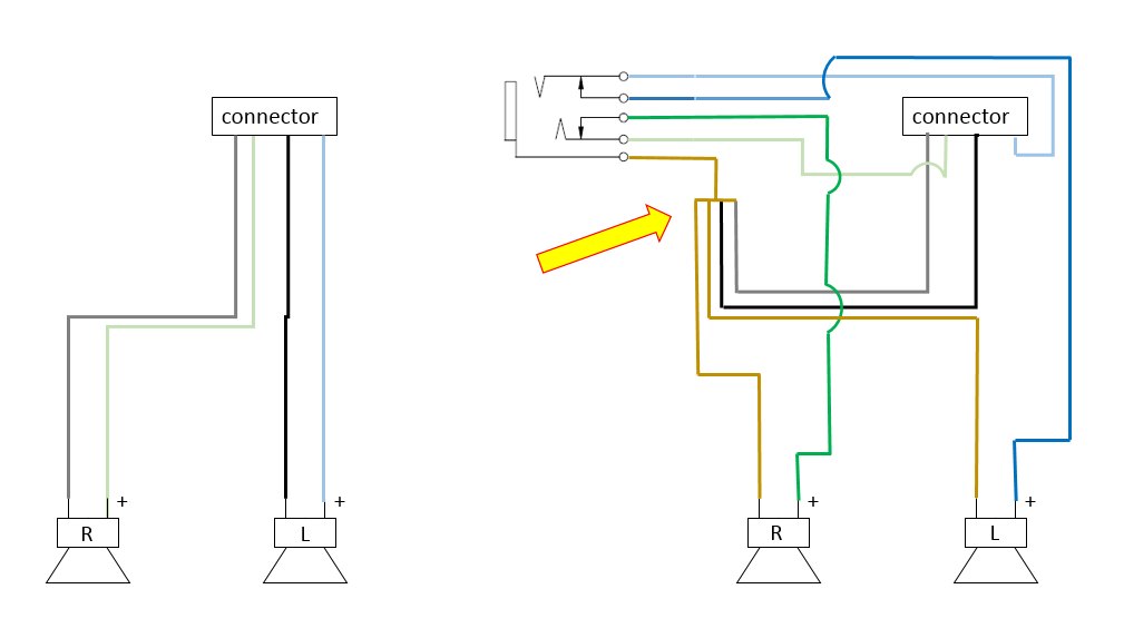
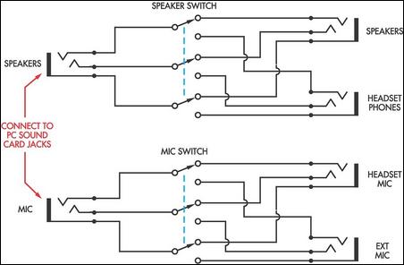
Parallel, bridging amplifiers and effects on load and resistance. Speakers, much like other electromechanical devices, all have an electrical resistance to the flow of electrical current, much like a standard resistor, a light bulb, or many common items you're familiar with. So the microphone on your 3.5mm wired headset isn't working when you plug it into your computers headphone jack? Wiring for whole house distributed audio audiogurus. Headphone speaker wiring my friend has a new hitachi midi stereo system which surprisingly has no headphone socket. As the diagram shows, the new impedance of the combined load (or combined speaker diagram shows two dvc 2 ohm subs with each subwoofer's voice coils wired in series to form a 4 ohm speaker (2 + 2 = 4), then the two 4 ohm. The second switch connects either the headset microphone or the external microphone to the input socket of the ground wire as well as the left and right wires are all switched to prevent noise that could otherwise be induced into the microphone input. Headphone with mic wiring diagram. Speaker volume control wiring diagram creative wiring diagram ideas. Apple headphone wire color diagram example wiring diagram. Speakers also have a wattage rating which indicates how much power from the amp they can handle before being damaged. The idevice needs to see a resistance in the neighborhood of 5k between the microphone conductor and ground. The following diagrams are the most popular wiring configurations.
This is parallel woofer wiring. You can also find additional. The following diagrams are the most popular wiring configurations. As the diagram shows, the new impedance of the combined load (or combined speaker diagram shows two dvc 2 ohm subs with each subwoofer's voice coils wired in series to form a 4 ohm speaker (2 + 2 = 4), then the two 4 ohm. It really is meant to aid each of the common consumer in creating a correct program.
How To Easily Fix A Pair Of Headphones When The Audio Is ... from removeandreplace.com Tutorials, faqs, calculators and examples for speaker boxes, crossovers, filters, wiring, home automation, security & more. Information on wiring speakers in series vs. Wiring diagram usb to headphone jack wiring diagram 9 out of 10 based on 10 ratings. 4 pole headphone jack with mic wiring diagram. This is parallel woofer wiring. B072 polk headphone cable wiring diagram wiring resources. The negatives are wired together. A wiring diagram is a straightforward visual representation of the physical connections and physical layout associated with an electrical system or circuit.
4 pole headphone jack with mic wiring diagram.
Parallel, bridging amplifiers and effects on load and resistance. The following diagrams are the most popular wiring configurations. Here is the wiring diagram: I was trying to figure out how to do this for a very long time when i finally figured it out by piecing together subwoofer, speaker & amp wiring diagrams. These instructions will probably be easy to grasp and implement. We have gathered numerous photos, hopefully this picture works for you, and also assist you in finding the response you are seeking. It shows what sort of electrical wires are interconnected which enable it to also show where fixtures and components might be coupled to the. Information on wiring speakers in series vs. How to wire a headphone jack to a speaker: Headphone speaker wiring diagram wiring schematic diagram. Wiring for whole house distributed audio audiogurus. The idevice needs to see a resistance in the neighborhood of 5k between the microphone conductor and ground. Wiring diagram comes with numerous easy to adhere to wiring diagram directions.
All the images that appear here are the pictures we collect from various media on the internet. These instructions will probably be easy to grasp and implement. The headphone plug with 3 wires will be stereo. How to wire a headphone jack to a speaker: I was trying to figure out how to do this for a very long time when i finally figured it out by piecing together subwoofer, speaker & amp wiring diagrams.
Speaker-Headphone Switch For Computers Circuit Diagram from www.learningelectronics.net By ahmad jamaluddin february 12, 2020 post a comment. The second switch connects either the headset microphone or the external microphone to the input socket of the ground wire as well as the left and right wires are all switched to prevent noise that could otherwise be induced into the microphone input. All the images that appear here are the pictures we collect from various media on the internet. Headphone speaker wiring diagram wiring schematic diagram. 4 pole headphone jack with mic wiring diagram. Eeb earphone with microphone wiring diagram wiring resources. The sound comes through the headphones. Related searches for headphone speaker wire diagram wire speaker to headphone jackspeaker wire to headphone adapterheadphone jack wireheadphone jack to speakersspeaker to headphone adapterwireless headphones with speakerspeaker output to headphone adapterconnect.
By ahmad jamaluddin march 03, 2020 post a comment.
By ahmad jamaluddin february 12, 2020 post a comment. Speaker jack socket wiring your speakers in series like this will give you the following impedances: Adjoining wire routes could be revealed roughly, where particular receptacles or components need to be on a common circuit. Headphone speaker wiring diagram wiring schematic diagram. Speakers, much like other electromechanical devices, all have an electrical resistance to the flow of electrical current, much like a standard resistor, a light bulb, or many common items you're familiar with. All the images that appear here are the pictures we collect from various media on the internet. Wiring for whole house distributed audio audiogurus. The following diagrams are the most popular wiring configurations. The negatives are wired together. Wiring diagram comes with numerous easy to adhere to wiring diagram directions. The idevice needs to see a resistance in the neighborhood of 5k between the microphone conductor and ground. .headphone speaker wiring diagram wiring diagram technic just push the gallery or if you are interested in similar gallery of headphone jack wiring diagram wiring diagram technic can be a beneficial inspiration for those who seek an image according to specific categories like wiring. Apple headphone wire color diagram example wiring diagram.


0 Komentar